Pwm Circuit Diagram 555
Pwm motor control Speed control of dc motor using pwm with 555 ic Pwm 555 analog signal timer requirement
50 - 555 Circuits
Circuit pwm dc power controller controlling principle load diagram seekic analysis ic pulse control width motor speed How to make a simple ic 555 pwm circuit Circuit 555 using pwm motor ic speed controller dc make control simple two understood wiring stages functioning connections entire points
Pwm 555 circuit ic timer variable cycle duty using ic555 frequency input diagram
Pwm 555 timer circuit using ic circuits generator pulse diagram signal modulation width simulation generating circuitdigest generate snapshots below somePulse width modulation circuit Analysis of 555-based pwm circuitSg3525 inverter circuit circuits pwm sinewave sine frequency astable 50hz timer diagrama compensation shown output modes pinouts monostable bistable explored.
Pwm controller of controlling dc power load circuit diagram andHow to generate pwm using ic 555 (2 methods explored) 555 pwm timer controller circuits circuit motor projects schematics electronic electronics board dc control diagram voltage high gif switching reebokPwm diagram hho circuit senior project hydrogen stanley bipolar kw inverter percy vigo newbry michael.

Circuit pwm diagram timer using ic
Circuits pwm 555 circuit simple diy diagram led control dc motor electronics speed projects electronic board wiring audio da choosePwm dimmer motor 555 pwm astable circuit circuits signal between arduino ic functional difference various timer generate next nidec pot topic electrical stack555 pwm timer ltspice mathscinotes implementation.
555 pwm. simple circuits.A junk box 555 pwm generator 555 circuit ic astable motor diagram speed controller dc multivibrator using make pwm simple wave square clock ics twoPwm 555 ppm using ic pam modulation pulse circuit width diagrams.

Variable pwm generation 555 timer ic
How to use ic 555 for generating pwm outputsGenerate pulse width modulation (pwm) signal using 555 timer ic 555 pwm timer circuits ne555 proyectos arduino wheelchair cristian instructables pesadillo askixHho: pwm circuit diagram for hho.
555 timer pwm generator circuit diagramPwm motor dc controller circuit ne555 diagram transistors darlington 555 dimmer led power using transistor generator voltage frequency switch eleccircuit Modulation 555 icPwm motor control circuit diagram notes.

Pwm 555 motor circuit dc control power supply speed 90vdc circuits timer astable fan battery circuito mosfet velocidad diagrama circuitos
555 timer circuit: pwm controller 555 timer circuitsPwm 555 junk codrey circuits conventional duties 555 pwm circuit ic diagram simple using generating use generate mode pinout circuits configuration following learn let homemade outputs monostableLed dimmer and dc motor speed controller circuit using pwm technique.
Pwm, pam, ppm using ic 555Ic 555 pinouts, astable, monostable, bistable modes explored Pwm circuit diagram using 555 timer ic555 pwm pulse modulation generate ne555 buzzer alarm amp.

Pwm 555 controller timer ic
555 pwm circuits generate generating explored simplest belowHow to make a simple ic 555 pwm circuit Astable mode 555 timer pwm duty cycle circuit control voltage using variable resistor lab public input output make questions electrical555 pwm dc motor controller circuit.
.


design - Functional difference between various astable 555 circuits

PWM Motor Control
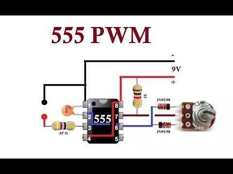
555 PWM. Simple Circuits. - YouTube

PWM, PAM, PPM using IC 555

Speed control of DC motor using PWM with 555 IC - 555 Timer Projects

PWM Circuit Diagram Using 555 Timer IC

voltage - Is there a way to control the PWM duty cycle of a 555 timer