Rectifier Stack Circuit Diagram
Zener bridge rectifier circuit diagram Rectification explained Zener circuit bridge diagram rectifier diode wiring diagramz
3 Phase Bridge Rectifier Circuit Diagram / Rectifier Theory 3 Phase
Rectifier inverter Circuit analysis Cascade rectifiers circuitlab
Rectifier bridge
Rectifier diodes transformer bridge polyphase allaboutcircuits phases circuits rectifiersCircuit design Single phase half wave rectifier- circuit diagram,theory & applicationsBuild a low forward drop rectifier circuit diagram.
Multisim rectifier wave circuit simulation tap3 phase bridge rectifier circuit diagram / rectifier theory 3 phase Rectifier bridge works does work resistor load figure derf stepFull wave rectifier circuit diagram in multisim / pcb design practical.

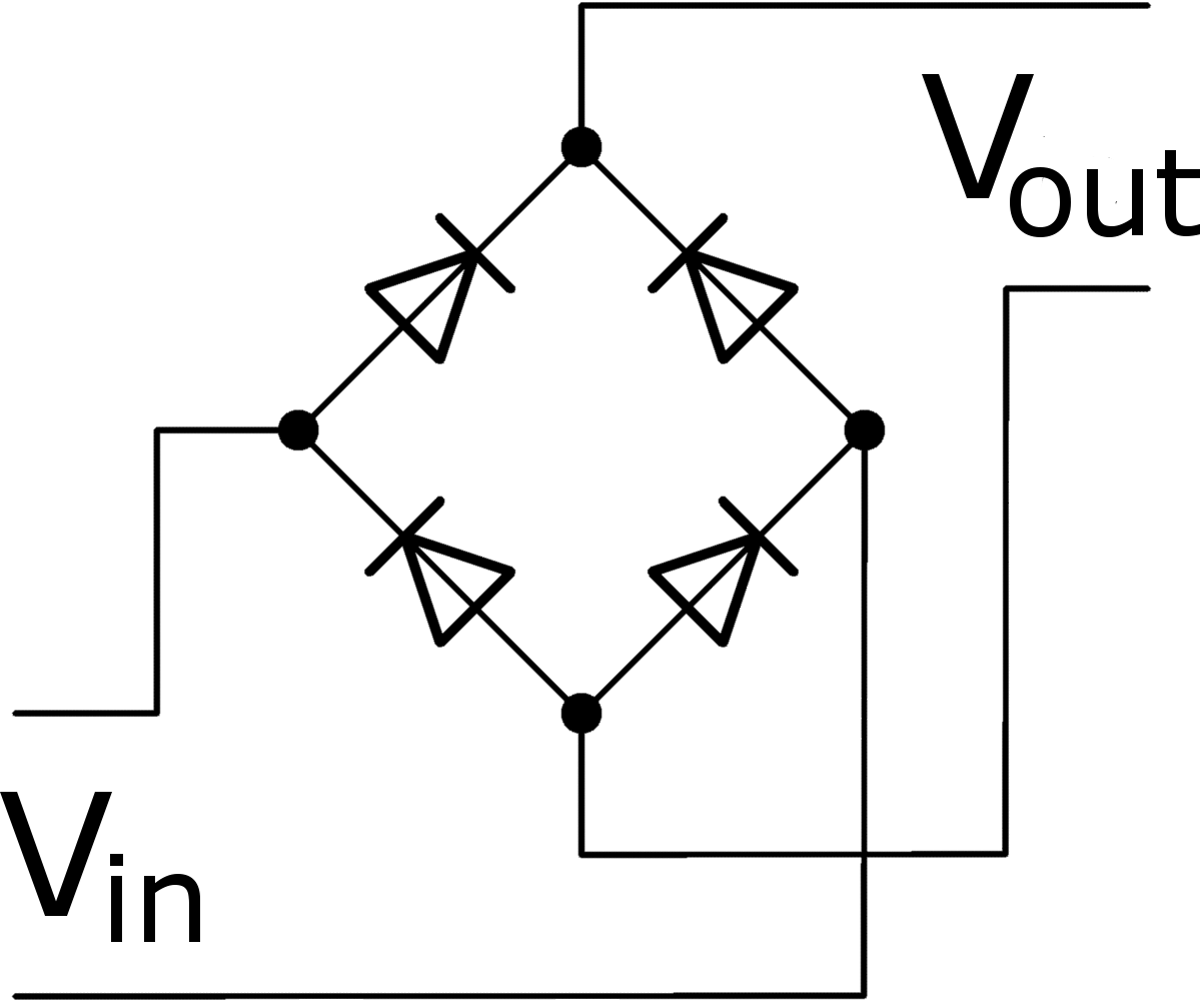
How a bridge rectifier works
Low voltage / high current rectifier using mosfetRectifier: what it is? how does it work? Rectifier circuit diagramBasic synchronous rectifier circuit..
Rectifier synchronousRectifier transformer waveform tapped etechnog Single phase inverter circuit under rectifier load with rc filterFull-wave rectifier circuit.

Mosfet rectifiers voltage mosfets designing voltages diode efficiency simple exhibit
Rectifier rectifiers halves rectifies combining sequentiallyRectifier wave circuit half bridge ac dc basics Rectifier circuit bridge diode types power rectifiersMosfet rectifier low.
Rectifier circuit diagramHalf & full wave rectifier Rectifier diode rectification novicesRectifier circuit diagram wave output waveform input.


Single phase inverter circuit under rectifier load with RC filter

Zener Bridge Rectifier Circuit Diagram

circuit analysis - Cascade multiple Full-bridge Rectifiers Connected to

circuit design - Designing MOSFET bridge rectifiers for high voltages

Single Phase Half Wave Rectifier- Circuit Diagram,Theory & Applications

3 Phase Bridge Rectifier Circuit Diagram / Rectifier Theory 3 Phase

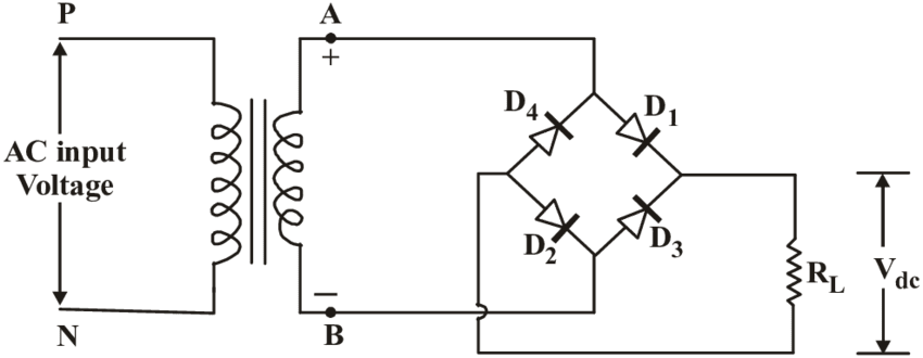
Rectifier Circuit Diagram | Half Wave, Full Wave, Bridge - ETechnoG
Rectification Explained | Electronics for novices
Rectifier - Altron Automation Learn PLC Programming