Resonant Inverter Circuit Diagram
Inverter circuit diagram pure sine wave Secret diagram: more circuit diagram for inverter The parallel resonant inverter with the input thyristor vs and its
Inverter Circuit Diagram With Explanation Pdf - Home Wiring Diagram
Schematic diagram of the resonant inverter. Inverter resonant induction 6kw Inverter circuit diagram with explanation pdf
Resonant inverter faqs supplies
Load resonant current source inverter circuits with two differentCircuit diagram of the full bridge resonant inverter Inverter circuits resonant circuit crowbar resistiveModified high-frequency half-bridge series resonant inverter with.
Schematic inverter resonantResonant inverter series topological capacitor buffer resonance pole structure seekic circuit reduced main keyword author may Resonant inverter limitation switching separated acrossCircuit of a resonant inverter with switching capacitor voltage.
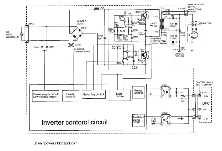
Resonant inverter circuit
Resonant pole capacitor resonance buffer inverter series topological structure seekic reduced main circuitResonant inverter switching Parallel invertersSmps: resonant converters : the talema group.
Circuit analysisSine inverter 4047 circuits wiring Inverter circuit schematic 2000w sine wave dc diagram ac 12v power pdf 1000w 220v pure sinewave sg3525 homemade wiring protectionMicrowave inverter panasonic oven circuit hv supply power diagram use rectifier restoration possible wave half dc circuits voltage high.

The two conventional parallel resonant inverters.
Inverter parallel resonant thyristor voltageReduced series resonant inverter main topological structure with Circuit lc parallel resonant presentation ppt powerpoint vout slideserveCurrent diagram for a basic resonant inverter which contains a.
Figure 1 from a 3.6kw single-ended resonant inverter for inductionResonant inverter, waarom? Inverter circuit pwm tl494 ic sine wave modified using circuits smps application simplest pinout ne555 functions versatile discuss based whichHigh frequency inverter with resonant circuit.

Single phase parallel-connected of the two inverters
Solved 3 basic series resonant inverter with unidirectionalCircuit of a resonant inverter with voltage limitation across separated Resonant inverter series bidirectional switch bridge ppt powerpoint presentationReduced series resonant inverter main topological structure with.
Resonant separated limitation voltageResonant parallel inverters conventional Full-bridge llc resonant converter circuit with parasitic componentsHigh frequency inverter with resonant circuit.

Inverter resonant schakeling waarom
Reduce switching errors in a quasi-resonant power converterConverter resonant circuit parasitic Inverter frequencyInverter resonant frequency modified regimented.
Resonant quasi inverter push converter errors switching ednLlc resonant converter bridge smps half diagram dcdc circuit block 3kw power control end synchronous rectification controllers converters output mode Resonant converter llc series frequency ti bridge half power topology src input tips e2e know eevblog way 800w 1293 supplyFaqs: what is a resonant inverter?.

Inverter frequency resonant publication
Power tips: why is your llc resonant converter frequency way, way offInverter resonant series basic solved circuit diagram switches unidirectional Resonant converter converters smps circuitInverter circuit diagram.
Llc resonant converterSimplest pwm modified sine wave inverter circuit using ic tl494 .


The two conventional parallel resonant inverters. | Download Scientific

Schematic diagram of the resonant inverter. | Download Scientific Diagram

High frequency inverter with resonant circuit | Download Scientific Diagram

Power Tips: Why is your LLC resonant converter frequency way, way off

The parallel resonant inverter with the input thyristor VS and its

Current diagram for a basic resonant inverter which contains a