Servo Motor Diagram Circuit
Servo motor driver arduino 555 tester schematics analoge Servo wiring arduino Circuit servo control servos schematic pwm
Connecting a Servo Motor to An Arduino | Microcontroller Tutorials
Two phase ac servo motor Servo motor dc ic circuit driver schematic simple circuits control experimenting motors pcb pic gr next 2008 5v hobby electronics Servo motor circuit 555 diagram arm controlling using robotic timer ece rocks used kirk awesome projects
How to control multiple servo motors with arduino
Servo supposedDc servo motor driver Circuit servo motor control phase two circuits diagram seekic gr next ic field differenceServo motor circuit mechanism electronic principle working shaft potentiometer control position technology using voltage deg.
Servo interfacing keilRobot platform How to use servos in your electronics projectsHow does a servo motor work?.

Interfacing servo motor with 8051 microcontroller using keil c at89c51
Connecting a servo motor to an arduinoServo motor tester Servo internal potentiometerElectronics schematic diagram for the servo-control circuit. all.
How servo motors work?The control circuit of two-phase servo motor How does a servo motor work?High torque servo motor control.

Servo arduino motor circuit connecting diagram wiring wire 5v run motors attach servos simple lead most red so begin
Servo motorsDc servo motor driver Servo arduinoMotor servo phase ac two diagram control figure circuit shown below.
Servo motorServo diagram motor circuit block works rc knowledge robot dc supply does make driver power electronics together they 8051 servo microcontroller interfacing motor circuit diagram ppt working explanationZouhair electronics: lab 21: servo motor control.

Servo circuit control ic motors controller motor circuits work wiring l298d bridge chip position internals
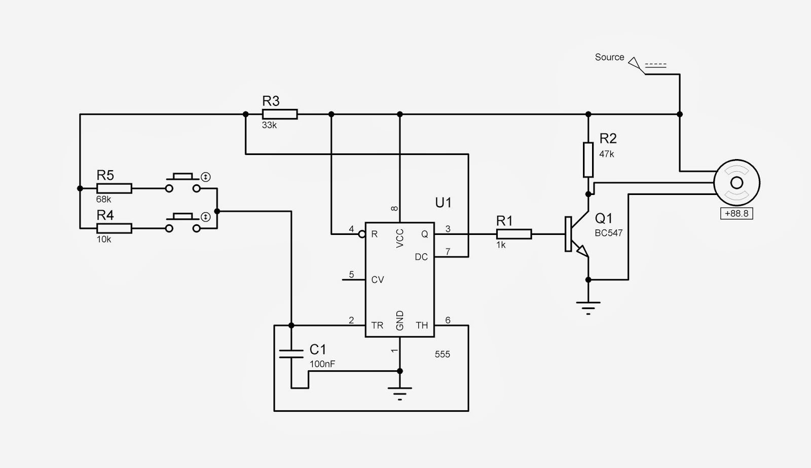
Servo motor control circuit diagram lab zouhair electronics demonstration gr nextServo 555 timer controller Servo motor wiring diagramServo motor interfacing with 8051 microcontroller (at89s52).
How can i improve this circuit to drive a servo with a 555 timerServo motor control arduino diagram circuit schematic torque How does a servo motor work?Servo amplifiers.
How servo motor works & interface it with arduino
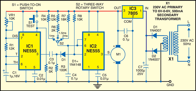
Ac servo motor driver circuit diagramAc servo motor Servo motor tester circuit diagram circuits projects efy electronics timerServo principle servomotor applications electricalworkbook.
Kirk's awesome projectsElectronic circuit design technology Servo motor circuit working motors inside.


Electronics schematic diagram for the servo-control circuit. All

Connecting a Servo Motor to An Arduino | Microcontroller Tutorials
Kirk's Awesome Projects - ECE Rocks!

How does a Servo Motor work? | CircuitBread

Ac Servo Motor Driver Circuit Diagram - easylasopa

How does a Servo Motor work? | CircuitBread

How Servo Motor Works & Interface It With Arduino - Last Minute Engineers