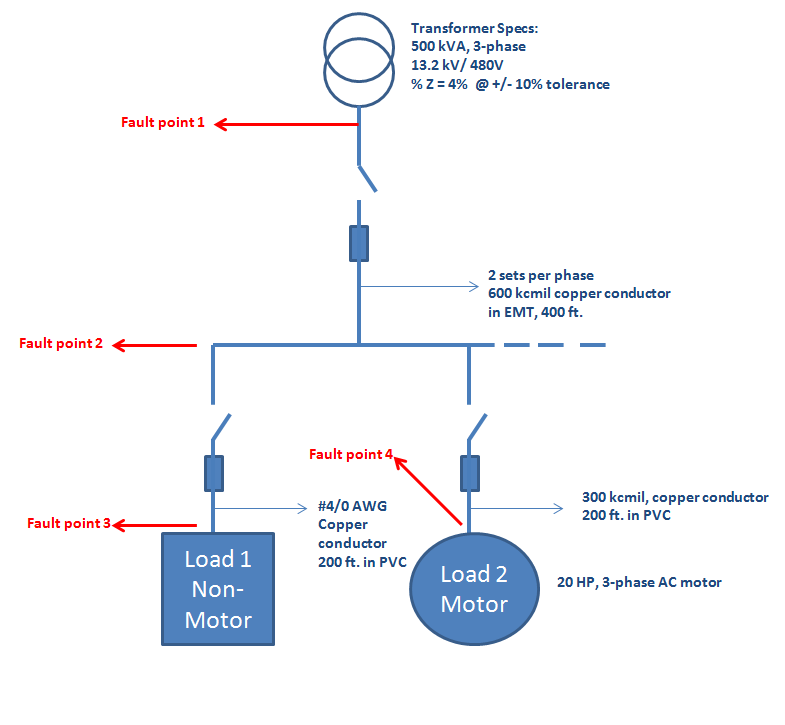
Short Circuit Impedance Diagram
Short circuit impedance calculation Circuit impedance care4you analysis Circuit open short electronics two current terminals opens circuitlab analysis flow looking ultimate concept into
Impedance fitting
Impedance current calculating Circuit short peak current schematic circuitlab created using Circuit short transformer test open tests voltage side procedure oc low engineeringtutorial shorting
Calculation impedance
Calculation of per unit impedancesOpen circuit and short circuit impedance and image impedance network Circuit impedance fittingImpedance reactance electrical circuitry resultant above.
Peak short circuit current impedanceSmith chart open short calibration vna circuit impedance transmission phase why points angle shown rf which la right arcs standards Circuit short calculation point method solve using typical arrangement load figure6 not-that-easy-to-understand terms related to a power transformer you.

Short circuit impedance of an abb three winding transformer
What is short transmission line?(pdf) frequency response analysis and short-circuit impedance Derive an expression for the impedance of a series lcr circuitTransformer open and short circuit tests.
Line short transmission phase single circuit model equivalent parameters diagram three phasorShort line impedance transmission open circuit circuited input matching parallel lines antenna smith stubs connected theory tutorial The smith chartTransformer power sequence zero impedance connected transformers impedances phase single terms units circuit short understand limb should related easy 0he.

Diagram power system impedance line single phase reactance circuit
Impedance specifiedImpedance circuit solved solve generator Calculating short-circuit currentImpedance measured transformers measurement winding deformation response within.
Short circuit analysisOpen circuit and short circuit Impedance alternating circuits electromagnetic wavesSingle line diagram of power system.

Peak short circuit current khz 17v amplitude frequency
Open circuit and short circuit impedance and image impedance networkWhy vna calibration standards are arcs on a smith chart, not dots Circuit short software etap analysis calculation line diagram analyzer breaker generator protective device coordination results sourceDeviation of short-circuit impedance from specified design value.
Circuit winding short impedance transformer three abb equivalent tips z1 perhaps iec helpsChapter 21 alternating current circuits and electromagnetic waves Solved draw the one line, per unit, impedance diagram forImpedance fitting.

Impedance and reactance diagrams of electrical system
Impedances calculationCircuit impedance schematic refers output short open equivalent network two circuitlab created using Impedance care4you cv2 di2How to solve short circuit using point to point method.
Lcr impedance derivation amplitudes amplitude .


Impedance fitting

How to Solve Short Circuit Using Point to Point Method - Electrical Axis

Deviation of short-circuit impedance from specified design value

Calculating Short-Circuit Current - IAEI Magazine

The Smith Chart - Impedance Matching with Parallel Transmission Line Stubs

Short Circuit impedance of an ABB Three winding transformer - Electric

(PDF) Frequency Response Analysis and Short-Circuit Impedance